
The Problem
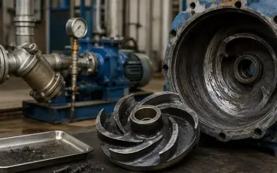
A customer was experiencing two main issues with a Fybroc Series 1600 2x3x6 pump: the pump was becoming hot during operation and the flow rate was lower than expected. The original duty point provided by the customer was 35 m³/h at 20.9 m head, approximately 2 bar, and the pump had been selected based on this requirement.
When our team visited the site to troubleshoot the system, the actual installation conditions were reviewed. One important finding was that the 3-inch discharge pipeline from the pump to the tank was estimated to be about 150 metres long.
Because the discharge piping near the pump was too short, there was not enough space to install an ultrasonic flow meter. As an alternative, the team proposed connecting a control valve and hose at the blind flange and using the underground tank volume together with filling time to estimate the actual pump flow. This arrangement is shown in the site photos on page 2 of the case study.
What We Found On Site
During the inspection, water drained from the pump casing priming valve was found to be hot. At the same time, the motor current was measured at 8.3A, equivalent to approximately 5.223 kW, which was in line with the pump curve. This indicated that the motor and pump were operating, but the system was not allowing the pump to achieve the required duty point.
Another important observation came from the discharge pressure gauge. The gauge showed approximately 2.8 bar, and the reading remained around 2.8 bar even when the discharge valve was completely closed. The case study notes that this value was close to the pump’s zero-flow head.
When the discharge line blind flange was opened and the water was drained, the water at the priming valve returned to ambient temperature. This suggested that, before draining, the water had been circulating internally inside the pump casing with little or no effective discharge. This internal circulation was the reason the water temperature continued to rise.
Finding the Root Cause
The main issue was not simply the pump itself, but the actual resistance of the piping system.
Based on the site estimation, the long 150 m pipeline, approximately 10 m tank height, around 13 fittings and elbows, additional allowance and discharge requirement resulted in an estimated total head loss of at least 4.52 bar. This was much higher than the original 2 bar differential pressure used for pump selection.
As a result, the existing pump head was insufficient to overcome the actual system resistance. The pump therefore could not reach its intended duty point, causing internal fluid circulation and the increase in fluid temperature.
Winston Engineering Recommended Solution
The recommendation was to increase the pump speed to approximately 3,500 rpm using a Variable Frequency/Speed Inverter and to increase the motor size to 11 kW so that the pump could achieve a higher discharge head.
This case shows why pump selection should consider the complete system, not only the required flow and discharge pressure. At Winston Engineering, our team can support customers with site troubleshooting, pump performance checks and system condition reviews to identify the actual cause of problems such as low flow, overheating or insufficient pressure, and recommend a practical solution for the application.

Author Bio
Chun Wei

Chun Wei is a marketing professional with a Bachelor of Arts in Marketing from UCSI University. With hands-on experience spanning social media management, data analysis, and sales marketing, he brings a fresh and analytical perspective to content and digital strategy. His background across various industries has sharpened his ability to translate insights into effective marketing initiatives. At Winston Engineering, Chun Wei contributes to the team's mission of putting solutions in action through clear, engaging, and informative content.
See all posts by Chun Wei »